
Duct Cfm Chart Metal Duct Friction Loss Calculator 1 Enter Duct Airflow CFM Duct Velocity FPM Duct Length and the number of bends 2 Read Round Duct Diameter inches and Friction Loss Per 100 of duct inches of water Installation Instructions Field Measurement Duct Cfm Chart virginiaair available forms Residential Duct Sizing Guide pdfResidential Duct Sizing Guide Key Points to Remember when using this guide The sizing chart is designed for estimating the airflow in an average system The chart assumes the blower motor and total effective length of CFM Duct Height Inches Equivalent Round
reference Heating CoolingA duct calculator measures air velocity by using a formula in which air flow is a variable expressed in cubic feet per minute or CFM Heating ventilation and air conditioning professionals commonly use duct Duct Cfm Chart Duct Sizing Guide The following duct sizes are based on a fraction drop of 10 inches per 100 feet of lineal duct This Equal Friction method of duct Size Duct Diameter Sizing Charts The following is needed to determine the duct diameter CFM and Velocity CFM V AREA Charts listed below show what duct diameter to use given a CFM and Velocity
Duct Sizing ChartStep One Identify the volume of air that will be passing through the duct Step Two Select the duct size from the table that can carry that volume of air Step Three If desired airflow exceeds the CFM rating increase to the next duct size Step Four Listed CFM is based on typical field Duct Cfm Chart Size Duct Diameter Sizing Charts The following is needed to determine the duct diameter CFM and Velocity CFM V AREA Charts listed below show what duct diameter to use given a CFM and Velocity efficientcomfort asp ResDuct Web ResDuct Web aspRectangular duct is rounded up to the nearest 1 4 inch Calculations are for 60 F dry air at sea level from 5 to 3000 cfm approximately standard air which is 0 075lb da ft If ASHRAE 2013 is selected Flexible roughness is 0 003 ft when straight and fully stretched tight at 0 compression adjusted at other compressions otherwise the
Duct Cfm Chart Gallery

DuctChart, image source: eng-hvac.blogspot.com
hvac duct sizes duct size calculator excel low medium velocity chart, image source: skepticrant.com


EQUIVALENT+ROUND+DUCT+SIZES, image source: slideplayer.com

tdchart, image source: www.atrendyhome.com
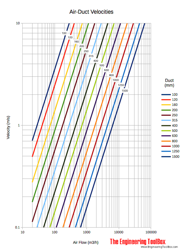
air duct velocity diagram 2, image source: www.engineeringtoolbox.com
maxresdefault, image source: www.youtube.com
detailed cooling chart, image source: www.myhvacperformance.com
Static Pressure Test %20Locations_3, image source: dolap.magnetband.co

OR blower chart, image source: homeenergypartners.com

turning vane 1, image source: www.tlj-eng.com

vacuum pipe air velocity diagram cfm, image source: www.engineeringtoolbox.com

duct design 12 638, image source: www.slideshare.net

screen shot 2012 08 19 at 7 42 21 pm, image source: russellking.me

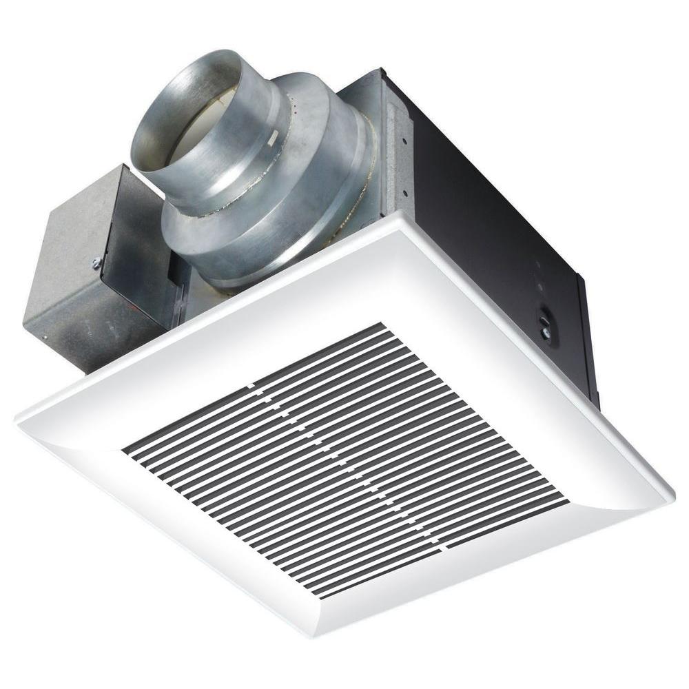
white panasonic bath fans fv 11vq5 64_1000, image source: www.homedepot.com

maxresdefault, image source: www.youtube.com

Specific impulse kk 20050824, image source: commons.wikimedia.org

csm_Table_3_E_b1015c1b2a, image source: corporate.armacell.com
fss1_ext_chart, image source: www.odicis.org

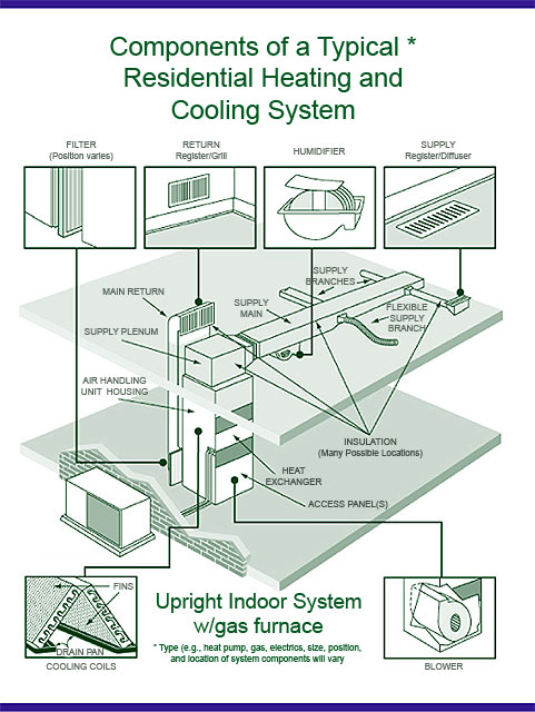
airducts_components_lg, image source: www.epa.gov
M0vle, image source: diy.stackexchange.com

0 comments:
Post a Comment